×

Search
The test hydraulic machine is used for hydraulic sealing test of φ254 ~ φ508 pipes. It adopts manual control and is independently designed and developed by our technical staff.
Test tube diameter: Φ254 ~ Φ508mm
Test tube length: 12000 ~ 18288mm
Maximum test pressure: 13MP
Sealing method: sealing ring seal
Test medium: water
The hydro pressure testing machine is mainly composed of three parts: hydraulic press body, water supply system and hydraulic station.
Including: main beam, fixed support, moving support, moving sealing head, pipe clamping device:
1.1. There are three main beams. One end of the three beams is connected to the fixed support by the stud, and the other end is supported by the moving support to withstand the axial force generated by the water pressure in the pipe during the hydraulic test.
1.2. Fixed support:
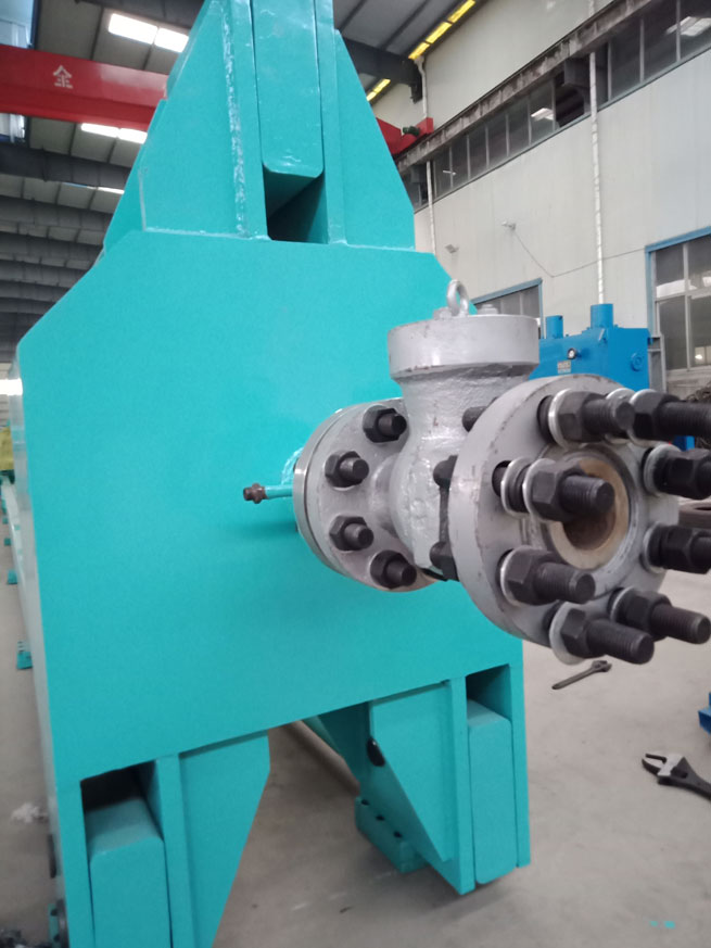
Located at the positioning end of the pipe and the main beam are connected by six studs, which are equipped with a water filling valve, a booster pipe, and a pressure transmitter. The pipe can be filled with water through the water filling valve and pressurized through the booster tube. The pressure boosting process is displayed by the pressure transmitter.
1.3. Moving support and moving sealing head:
The moving support and the moving sealing head are connected by an oil cylinder. The moving support can be moved on the beam according to the length of the pipe, and moved to a suitable position and fixed with a stud. An air release valve is installed on the moving seal head for releasing when the pipe is filled with water. After the clamping device clamps the pipe, the sealing head is moved and moved by the oil cylinder to clamp and seal both ends of the pipe.
1.3.1. Exhaust valve:
The exhaust valve is used to exhaust air when filling the pipe with water, and to release pressure after the test is completed.
Exhaust valve

1.4. Clamping device:
The clamping device integrates the centering of the tube, blocking and pushing the pipe, clamping the pipe, and is placed at the two ends of the pipe on the bottom beam of the hydraulic press. The position is fixed by the set screw to adjust the position of the pipe, and then the pipe is clamped. As shown in the figure below, there is an air pressure adjustment valve on the clamping device, and the clamping force of the clip can be adjusted through the air pressure adjustment valve. Matching with the clamping device, there are two types of height-enhancing plates, one large and one small. The height-enhancing plates installed above the clamping device. Used to test pipes with a diameter of 508 mm when no height plate is installed, used to test pipes with a diameter of 325 mm when small height plates are installed, and used with pipes with a diameter of 254 mm when a large height plate is installed.
Clamping device

The water supply system is divided into two parts: water injection and pressurization. After the pipe is fixed and sealed, the filling pump for water injection is turned on to inject water into the pipe and the water tank. When the pipe is filled with water, close the exhaust valve and open the high-pressure booster pump to pressurize the pipe.
Infusion pump
Pipe od | power | flow | frequency | Synchronous speed | phase | voltage | electric current |
50MM | 2.2KW | 15m2/h | 50HZ | 3000r/min | 3 | 380V | 6.5A |
High pressure booster pump
export | delivery | medium temperature | Inlet pressure | motor | Pump rotate speed | flow | Plunger diameter | Plunger distance of travel |
13MP | water | normal temperature | 0.2~0.5MP | 11KW | 350r/min | 40L/MIN | 35mm | 40mm |
The hydraulic station consists of an oil tank, an axial plunger pump, and a three-phase asynchronous motor.
Axial plunger pump
Nominal displacement | Rated pressure | Rated rotate speed |
63ml/rew | 31.5MP | 1500r/min |
Three-phase asynchronous motor
Power | Rotate speed | Voltage | Rated current | Frequency |
18.5KW | 1475r/min | 380V | 35.3A | 50HZ |
When you start using it. The following parts should be located with the original parts, namely:
1. According to the length of the pipe, fix the movable support to the corresponding hole of the beam with a pin.
2. The main cylinder returns.
3. The clamping device is opened.
4. The exhaust valve opens.
5. Install sealing rings on both ends of the pipe.
6. Install the heightening plate according to the diameter of the pipe.
Block the pipe
↓
clamp
↓
Move the moving sealing head to clamp and seal the two ends of the pipe
↓
Turn on the perfusion pump to fill water to the water tank and pipe
↓
After filling with water, close the exhaust valve and open the high-pressure booster pump to pressurize
↓
Pressure holding
↓
Pressure relief drainage
↓
Sealing head return
↓
Open clamping device pressure test completed
1. After the pipe is transported, press the button 6 (block the pipe) in photo 2 to start the device 1 (block-push pipe) in photo 1 to take over the pipe.
2. After the pipe is taken over, press the button 8 (clamp clamping) in photo 2 to start the device 2 (clamp) in photo 1, and the device 2 will clamp the pipe back.
3. Press button 11 (oil pump start) in photo 2 to start the oil pump, and then press button 2 (Sealing disc advance) in photo 2 to advance the head to seal both ends of the pipe.
4. After the two ends of the pipe are sealed, press button 13 (water injection start) in photo 2 to start the irrigation pump. The irrigation pump will inject water into the pipe. At this time, the exhaust valve should be in the open state. Button 4 (exhaust valve open) in photo 2 is the exhaust valve open button ,button 3 (exhaust valve closed) is the exhaust valve close button. If the exhaust is not open, the gas in the pipe will not be discharged, then the irrigation pump can not fill the pipe with water.
5. When the pipe is filled with water, press button 3 (exhaust valve closed) in photo 2 to close the exhaust valve, then press button 14 (Water injection stop) to turn off the irrigation pump, and finally press button 15 (.Boost pressure start) turn on the high-pressure booster pump to pressurize the pipe. When the pressure in the pipe reaches the set value, the high-pressure booster pump will automatically stop.
6. When the pressure holding time is reached, press button 4 (exhaust valve open) in photo 2 to open the exhaust valve and release the pressure in the pipe. When the pressure is relieved, press button 1 (Sealing disc back) in photo 2 to retract the Sealing disc.
7. After the water in the pipe is emptied, press button 7 (clamp released) in photo 2 to release the clamp, and then press button 5 (push the pipe) in photo 2 to send the pipe away.
Photo 1
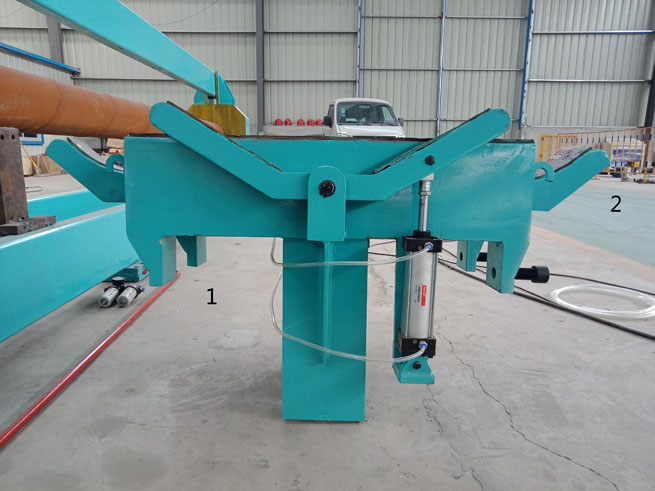
1. Block and push pipe 2. Clamp
Photo 2

1. Sealing disc back 2. Sealing disc advance 3. exhaust valve closed 4. exhaust valve open 5. push the pipe 6. block the pipe 7. Clip released 8. Clip tightening 9. Power indicator 10. Emergency stop 11. Oil pump start 12. Oil pump stop 13. Water injection start 14. Water injection stop 15. Boost pressure start 16. Boost pressure stop
2. Display screen:
Photo 3

Photo 4

on the value to be changed and an input box will pop up (photo 3). At this point, you can enter the value.
1. Current value of water pressure: real-time display of water pressure in the pipe, you can observe the change of water pressure in the pipe.
2. The current value of oil pressure: the oil pressure of the main oil cylinder is displayed in real time, and the oil pressure change of the main oil cylinder can be observed.
3. High-pressure water pump: displays the status of the high-pressure booster pump.
4. Main cylinder forward: Displays the state of the main cylinder when it is advancing.
5. Exhaust open: Display the status of the exhaust valve.
6. The initial pressure of the main cylinder (KP): the maximum pressure when the main cylinder moves forward. When this pressure is exceeded, the cylinder stops advancing to prevent damage to the pipes (the main cylinder initial pressure can be set according to demand).
7. Maximum pressure (KP): The pressure tested in the pipe. When the pressure in the pipe reaches this value, the high-pressure booster pump will automatically stop pressurization (the highest pressure can be set according to demand).
8. Water pressure setting value and oil pressure setting value: The water pressure setting value and the oil pressure setting value correspond to each other. The oil pressure of the main oil cylinder is increased as the water pressure increases, to prevent damage to the pipe caused by excessive oil pressure or seal leakage due to too small oil pressure.
The pipe pressure testing machine USES three - phase four - wire L1L2L3 to connect the fire line N to the zero line.
Line number corresponding to total power supply
L1 | L2 | L3 | N |
The oil station and electric distribution box are connected by three wires.
Line number corresponding to the oil station
U1 | V1 | W1 |
The high-pressure booster pump and electric distribution box are connected by three wires.
Corresponding line number of high-pressure booster pump
U2 | V2 | W2 |
The irrigation pump and the electric distribution box are connected by three wires.
irrigation pump
U3 | V3 | W3 |
Other parts corresponding line are marked with number in electric distribution box
Line number table
Main cylinder (forward) | Main cylinder (back) | exhaust | tightening | Over flow | 24V+ | 24V- | 1 | 3 | 2 | 4 |
Line NO
CHIESE | 主缸 | 排气 | 夹料 | 溢流 |
ENGLISH | Main cylinder | exhaust | tightening | Over flow |
Line number of oil pressure transmitter

Corresponding diagram of the line number of the water pressure transmitter

Photo 5: pressure transmitter
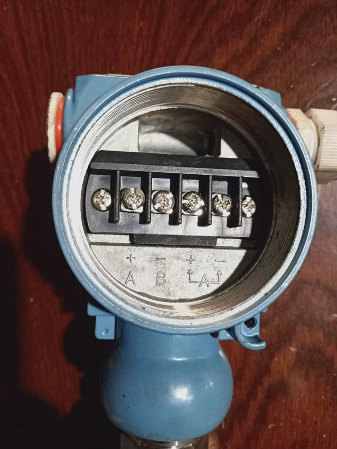
Photo 6
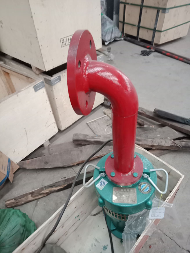
Photo 7
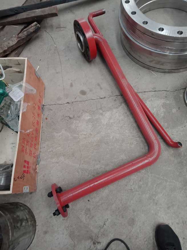
Photo 8:single valve
No 1 in photo 7 is connected to the single-valve in photo 8, No 2 of photo 7 is connected to the irrigation pump in photo 6, and No 3 of photo 7 is connected to the water tank.
Photo 9:water tank
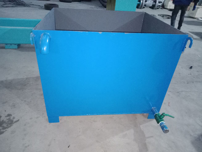
Photo 10 High pressure boost

High pressure booster pump
The single-stage valve in photo10 is to prevent backflow of water during pressurization and holding.
1. Avoid misoperation as much as possible to avoid damage to the steel pipe making machine.
2. Do not idle the water pump.
3. The inside of the tested pipe should be cleaned to prevent the dirt from damaging the seals of each valve.
4. The pool should be cleaned regularly and the clean water should be replaced regularly.
Large Diameter Spiral Welded Pipe Production Line
Small Diameter Spiral Welded Pipe Production Line
Heavy Duty Spiral Welded Pipe Production Line
Thin Wall Spiral Welded Pipe Production Line
Stainless Steel Spiral Welded Pipe Production Line
Hydrostatic Pressure Testing Machine for Large Diameter Pipe
Hydrostatic Pressure Testing Machine for Small Diameter Pipe
Hydrostatic Pressure Testing Machine for Ultra High Pressure Steel Pipe
Chamfering Machine for Large Diameter Steel Pipe End
Chamfering Machine for Small Diameter Steel Pipe End
Double Station Chamfering Machine for Steel Pipe
Automatic Steel Pipe Chamfering Machine
High Frenquency Welded Pipe Production Line for Large Diameter Pipe
High Frenquency Welded Pipe Production Line for Small Diameter Pipe
Steel Pipe Conveyor
Steel Pipe Rotating Roller Table
Steel Pipe Puller
Steel Pipe Dropper
Steel Pipe Storage Rack
3PE Anti-corrosion Steel Pipe Production Line
Plastic Coated Steel Pipe Anti-Corrosion Production Line
Polyethylene (PE) Insulated Steel Pipe Production Line
Quick Links
Address
Tel
+86-0317-6213222Quick Links
Address
South Industrial Development Zone, Yanshan County, Cangzhou City, Hebei Province
Phone
+86-0317-6213222